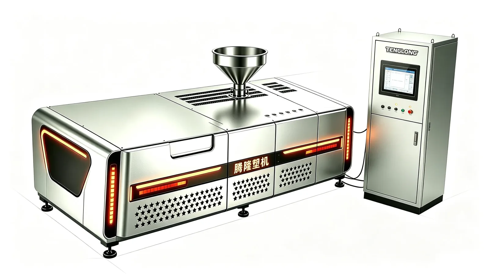
Summary: This walkthrough follows a twin screw granulator through its process: a chain of physical changes, each one governed by a number you can read off a spec sheet. It takes the material from hopper to silo across five stages — eight gravimetric channels meter the components within ±0.5%, six independently cooled barrel zones hold 190–260 °C while kneading blocks disperse the filler, two vacuum vents strip moisture from the filler at zone 8, the melt pump builds 60–120 bar behind a 60–80 mesh screen pack, and the melt is cut into 1.5–4 mm pellets at 1,500–3,500 rpm and dried below 0.2% surface moisture. The twin-screw specific mechanisms — surface renewal by kneading blocks, side feeding into a partly molten carrier, and devolatilisation that depends on a moving surface — are explained at each stage, together with the symptom that appears when the stage is off.

The material path and the clock
The published line runs in four steps — dose, melt and disperse, vent and pressurise, cut and dry — and the extrusion package sits in front of them. Flake enters through the feed throat, is metered by eight gravimetric channels at ±0.5%, is melted in a barrel of six independently cooled zones held at 190–260 °C, is mixed by kneading blocks while two side feeders and a liquid injection port add filler and additives, is stripped of moisture at the vacuum vents, is pressurised by the melt pump to 60–120 bar, and is cut into 1.5–4 mm pellets before the dryer brings surface moisture below 0.2%.
The clock is measured in metres of barrel, not minutes
A twin screw is not a long pipe with a heater in it. Residence time is set by the 40:1 L/D ratio and the screw diameter — roughly 2.5 m of working length on the 62.4 mm machine and 3.7 m on the 93 mm machine — combined with how fast the screw turns and how much feed you push through it. Every stage below occupies a defined stretch of that length, and moving a stage forward or backward is a screw configuration decision, not a machine one. The line itself is described on the TL-TS twin screw granulator product page.
Stage 1: metering and feeding
Nothing enters the barrel until the metering system has decided how much of each component enters it. The published system is eight-channel gravimetric dosing at ±0.5% per channel, with recipe management and batch traceability on the Siemens S7-1500, and loss-in-weight refill with a vacuum loader per component to keep those channels supplied.
Why gravimetric metering matters more than a volumetric screw. A volumetric feeder doses by volume, so bulk density changes the recipe silently: the same screw setting delivers a different mass when the flake density changes. A gravimetric channel closes its own loop on measured mass flow, so the ±0.5% is a statement about the recipe, not about the machine’s cleanliness. That is what makes a colour or a filler ratio repeatable from batch to batch, and it is why the control system keeps a batch record rather than just a setpoint. The broader differences between granulator platforms are in granulator types compared.
Two additions run in parallel with the main feed. The two side feeders take talc, glass fibre and CaCO3, and the liquid injection port takes silane, oil or flame retardant. Neither is decoration: the position at which a component enters the barrel decides what happens to it.
Stage 2: melting, and the six zones that hold the recipe
Flake does not melt in the feed throat. It is conveyed forward, compressed and melted over the first stretch of barrel, and the melt front is what the rest of the process acts on. The barrel is published with six independently cooled zones and deep-groove cooling bores with independent water circuits per zone, holding 190–260 °C.
Six zones is a profile, not a setting. Independent cooling exists because a compounding recipe needs a temperature gradient. The melting zone runs hot enough to homogenise the polymer, the mixing zone runs cooler to limit shear heating, and the zone before the die is set so the melt reaches the die at a temperature the pelletizer can cut. The deep-groove bores are the mechanical reason a gradient is possible: they put water close to the melt without a jacket, so one zone can run hotter than its neighbour.
This is also where the side feeders and the liquid injection port act. A side feeder discharges into a partly melted carrier, so the filler is wetted by polymer rather than landing as dry powder in a molten stream. A liquid injection port lets silane, oil or flame retardant enter the melt as a liquid that can be dispersed into the matrix. Both are process positions, set per recipe.
Stage 3: mixing and dispersing, where the twin screw earns its price
This is the stage a single screw cannot reproduce, and the mechanism is worth stating plainly. Segmented screws combine conveying elements, kneading blocks and reverse elements configured per recipe, so the machine can move material forward and stop it, fold it, and move it again.
Surface renewal is the whole mechanism
Dispersion is not melting. It is breaking agglomerates apart and wetting every particle with polymer, and both require fresh surface. Forward-conveying elements generate shear but little new surface; kneading blocks generate circulatory flow that renews surface repeatedly; reverse elements build pressure against the screw tip and create the back-mixing that folds material through that renewing zone. Change the element sequence and you change the dispersion, at the same rpm, on the same machine, in the same barrel.
That is what allows the published capability of 70% calcium carbonate into PP without burning the carrier, and 30% glass fibre into PP or PA6 without the fibre being destroyed — the fibres are carried in a circulating flow rather than dragged through a shear field. It is also why a filled or reinforced compound is a different process from plain melting. The same principle drives the colour and additive masterbatch work, where the TL-MB masterbatch granulator applies the same mixing architecture at concentrate strength.
Stage 4: devolatilisation and filtration
Before the melt reaches the die, the volatiles have to leave. The published machine has two vacuum vents and a vent at zone 8 that removes moisture from the filler, so the moisture leaves at a known point rather than surprising you in the die.
Devolatilisation needs a moving surface. A vacuum vent does not remove water from a static melt; it removes vapour from the surface that the melt presents to it. That is why venting is a twin screw capability and not just an equipment option: the elements have to keep renewing the surface inside the vented zone while the vacuum pulls. The published answer to genuinely high volatile levels, 5,000 ppm, is two-stage devolatilisation at high surface renewal, and a vent with a static melt behind it will not get there.
Filtration comes next, and it is where the material decides the configuration. The published options are a hydraulic screen changer or a melt pump with a screen pack; unfilled compounds run a 60–80 mesh pack, while highly filled grades may run a melt pump and skip the screen altogether. The melt pump then builds 60–120 bar for a stable die feed, decoupling the die from the pressure the screw generates.
Stage 5: cutting, cooling and the exit
Two cutting routes are published on the same frame. Underwater pelletizing cuts at 1,500–3,500 rpm and the centrifugal dryer brings surface moisture below 0.2%, with pellet size at 1.5–4 mm. Strand pelletizing lets the melt leave the die as strands cooled in air and cut. Because both sit on the same frame, the route can change with the mix.
Why filled and reinforced grades favour underwater. The difference is not the knife. Underwater cutting forms the pellet surface in milliseconds, so there is no interval in which a hot, fragile, filled surface is dragged through air or bends fibres while the strand draws unevenly. For a reinforced compound, that surface quality is what keeps fibre length in the pellet and the cut face from breaking. For a clean, unfilled throughput stream, strand cutting is often simpler and cheaper — the published comparison of the cutting methods is in water ring versus strand versus underwater, and the strand line itself is on the TL-ST strand pelletizing line.
Where the timeline breaks
Each stage has a failure direction you can predict in advance. A melt temperature profile flat across the six zones produces poor dispersion. A vent that is not pulling produces foam at the die. A screen pack that is closing produces rising melt pressure and falling output. A side feeder discharging into a fully molten carrier produces agglomerates rather than dispersion. Each shows up at a different point in the chain, which is why the order of the chain matters when you diagnose it.
Two changeover times sit outside the barrel. A screw set change takes 4–6 hours, so a line running several product families needs one screw set per family, and a colour change takes about 40 minutes because co-rotating screws have no dead corners to clear. The process terms above are defined in the pellets and feedstock glossary, and if the feed arrives dirty rather than compounded, the upstream part of the same flow is covered in plastic recycling equipment.
| Stage | What physically changes | Published figure that governs it | Symptom when the stage is off |
|---|---|---|---|
| 1. Meter and feed | Eight channels meter the components by mass; side feeders and liquid injection add filler and additives | Eight-channel gravimetric at ±0.5% per channel; two side feeders; one liquid injection port | Batch-to-batch drift in filler ratio or shade; a starved side feeder |
| 2. Melt | Flake is conveyed, compressed and melted; the melt front forms and travels forward | Six independently cooled zones at 190–260 °C; deep-groove bores with per-zone water circuits | Unmelted pellets at the die, or a melt too hot for the recipe |
| 3. Mix and disperse | Kneading blocks fold the melt, renewing surface; reverse elements build pressure and back-mix | Segmented elements: conveying, kneading, reverse, configured per recipe | Agglomerates and visible specks; short fibre in a reinforced grade |
| 4. Vent | Moisture and volatiles leave from the surface the elements keep renewing inside the vented zone | Two vacuum vents, venting at zone 8; two-stage devolatilisation for 5,000 ppm | Foam at the die, bubbles in the pellet, a rising vacuum load |
| 5. Filter and pressurise | Contamination is removed; the melt pump decouples die feed from screw pressure | Hydraulic screen changer or melt pump with screen pack; 60–80 mesh; 60–120 bar | Rising melt pressure, falling output, pressure swings at the die |
| 6. Cut and dry | The melt is sheared into pellets and the surface water is removed | Underwater at 1,500–3,500 rpm; 1.5–4 mm pellets; surface moisture below 0.2%; or strand cutting | Dusty or deformed pellets; visible fibre breakage on reinforced grades |
Frequently asked questions
Q1: What happens in the first seconds of twin screw granulation?
Eight gravimetric channels meter the components to within ±0.5% each, the base polymer is conveyed and melted over the first stretch of a barrel held at 190–260 °C across six independently cooled zones, and the filler enters through the side feeders into a partly molten carrier. Everything downstream depends on those two steps being right: the melt front that forms here is what the mixing and venting stages work on.
Q2: Why does a twin screw disperse filler that a single screw cannot?
Because dispersion needs fresh surface, and the elements make it. Conveying elements move material forward, kneading blocks generate circulatory flow that repeatedly renews surface, and reverse elements build pressure that folds the melt back through that renewing zone. That is what allows 70% calcium carbonate into PP without burning the carrier and 30% glass fibre to stay intact instead of being cut.
Q3: How does vacuum venting actually remove moisture from a melt?
A vent does not pull water out of a static melt; it removes vapour from the surface the melt presents to it. The elements have to keep renewing that surface inside the vented zone while the vacuum pulls, which is why venting works on this machine and why the published answer to 5,000 ppm is two-stage devolatilisation at high surface renewal rather than more vacuum.
Q4: Why fit a melt pump on the line instead of running only a screen pack?
The screen pack and the melt pump do different jobs. A 60–80 mesh pack removes contamination and is right for unfilled compounds; a melt pump then builds 60–120 bar for a stable die feed and decouples the die from the screw pressure. Highly filled grades often run the pump and skip the screen, because abrasive filler destroys screen cloth faster than the economics justify.
Q5: How long does a product change take on a twin screw granulator line?
Two different numbers, and they belong to different plans. A colour change takes about 40 minutes, because co-rotating screws have no dead corners to purge. A screw set change takes 4–6 hours, because the element layout is part of the recipe. So one screw set per product family is normal practice, and the changeover time belongs in your production plan rather than in your process window.
Engineer’s note
The screw is what makes this process, and that is why our workshop started there. A kneading block smeared by abrasive filler changes the mixing behaviour long before it fails visibly, so element sets are treated as recipe items and rotated on inspection rather than run to destruction. Our screws are 38CrMoAlA, nitrided in-house to a 0.5–0.7 mm case at HV 900–1000, straightened to 0.03 mm runout, and aligned with barrel, gearbox and frame to 0.05 mm before the test run.
Engineering note: the numbers on this page are our own published reference ranges for the machine family, not a specification guarantee for any individual unit. Final output, specific energy and pellet quality are set by the incoming material, its moisture and contamination level, and the screen pack fitted. We write the confirmed figures onto the quotation after a factory test run on your own material.
Who wrote this
Zhou Gong (周工) is a senior plastic machinery engineer at TENGLONG Plastic Machinery in Linyi, Shandong. The factory was registered as Linyi Hedong District Tenglong Plastic Machinery Factory on 7 June 2016 and grew out of a screw and barrel workshop, so his work is rooted in the parts that decide whether a granulator holds output: screw geometry, nitriding case depth, barrel alignment and melt filtration. He prepares the technical specification for customer quotations, reviews the four-hour factory test data before shipment, and runs commissioning support on site. Screws are nitrided in-house to a 0.5–0.7 mm case at HV 900–1000 and straightened to 0.03 mm runout over the full length; barrel, screw, gearbox and frame are aligned to 0.05 mm before the test run.
Figures quoted here are engineering reference ranges published on our own product pages, not guaranteed values for any specific machine. Real output, specific energy and pellet quality depend on the incoming material, its moisture and contamination level, and the screen pack fitted. Final values are written after a factory test run on the customer’s own material, and the PLC-logged test report ships with the machine. For a quotation that reflects your material, send the feed form, contamination level and target output and a configuration comes back within one working day.
To see which stage will decide your output, send your formulation, filler load and target pellet size to the quotation request form and we will map the recipe — dosing, zone profile, vent position, screen pack and cutting route — back to you within one working day.