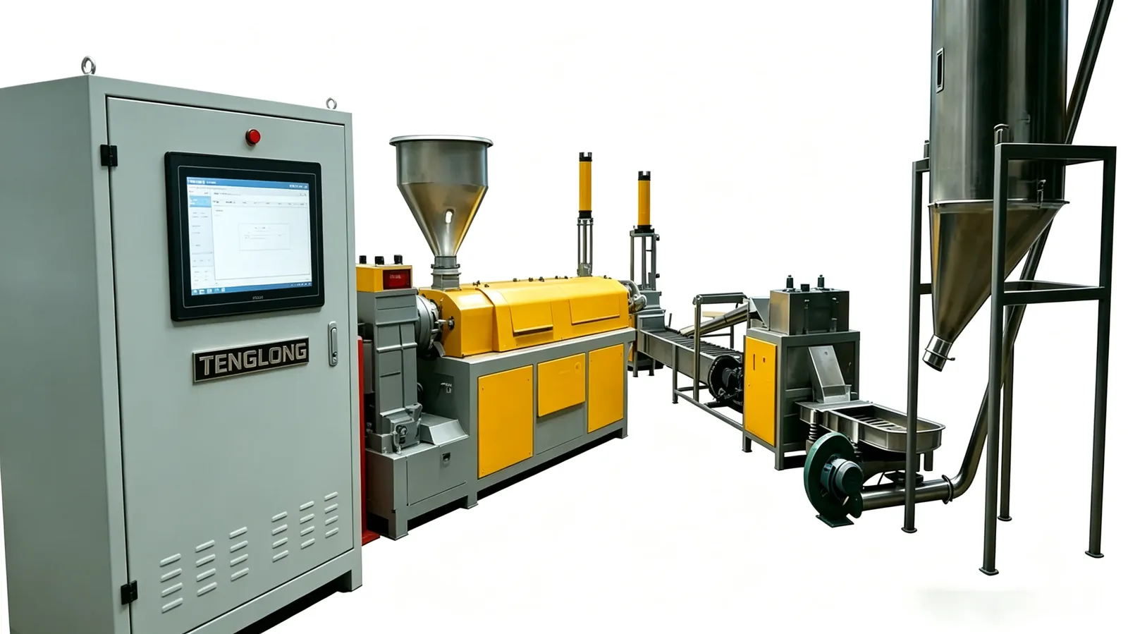
Summary: Underwater pelletizing is a chain of five physical steps, and each one changes the polymer state in a way you can measure. This walkthrough follows the material from flake to silo: the melt is brought to the die face, the water chamber is pressurised to 3–8 bar before the melt valve opens, the cutter shears the melt through 60–400 holes of 1.2–3 mm at 1,500–4,000 rpm, the hot process water at 40–90 °C quenches the cut pellets below 45 °C while carrying them to the dryer, and a centrifugal dryer throws off surface water in under two seconds to reach the published ≤0.1% moisture. Every step lists the published figure that governs it and what changes when you push that figure, so you can reason about a new polymer before you buy the line.

What actually happens to the strand, in ninety seconds
Flake enters the feed throat, is melted and filtered, reaches the die face inside a sealed water chamber, is sheared into pellets under water, is quenched while the circulating water carries it to the dryer, is dewatered centrifugally, and leaves pneumatically for the silo. The published description of the line runs in four steps — pressurise, cut at the face, quench and transport, dry and convey — with the extrusion step in front of it.
What makes this different from a strand line
What makes this different from a strand line is not the cutter. It is that the die face is submerged, so the surface of the pellet is formed in milliseconds instead of being exposed to air, gravity and slow cooling. The published line on the TL-UW underwater pelletizer page states the reason plainly: PET crystallises as it cools, PA absorbs moisture within seconds, and highly filled compounds smear on a knife. The pressurised cut answers all three at once.
Read the path below as a timeline rather than a list of parts. Each step hands the polymer to the next one in a defined state — hot, cut, wet, dry — and the published figure for each step is the control that keeps that state in range.
Step 1–2: melting, filtering and pressurising the chamber
The extrusion package melts the feedstock and pushes the melt through a screen pack, which is the last chance to remove contamination before the die face. Where a melt pump is fitted, it decouples the die pressure from screen condition and holds it within ±0.3%; without one, die pressure follows the screen and pellet size drifts 0.1–0.2 mm.
Why the chamber pressurises before the melt arrives
Meanwhile the water chamber fills and holds 3–8 bar before the melt valve opens. This ordering is the whole point of the design: the die face is already surrounded by pressurised water when the first melt appears, so the polymer never has a moment of unconfined, air-cooled surface. The pressure also shapes the cut — a die face under water keeps the strands standing as they are sheared, which is what produces round pellets rather than flattened ones.
At this stage the control loop is already active: cutter and water pressure cascade control keeps the two conditions matched as the load changes, and die-hole blockage detection with automatic cutter retraction is watching the cut from the first pellet.
Step 3: the cut at the die face
Knives pass the die plate at 1,500–4,000 rpm, shearing the melt through die holes of 1.2–3 mm, typically 60 to 400 holes in number. The result is a pellet of 1.2–3 mm with a published tolerance of ±0.15 mm, and it is cut in a submerged, pressurised chamber rather than in air.
Three variables move the quality of this cut
Cutter speed sets the shape: a slower pass suits larger pellets and a faster pass suits smaller ones, and the published 1,500–4,000 rpm range is wide enough to cover both. Hole count and hole diameter set the output rate and the size together. And melt temperature decides whether the cut shears cleanly or smears — the failure mode for highly filled compounds.
The pellet leaves the die already quenched, within milliseconds. That is why the published dust generation stays below 0.2%: there is no moment when a hot, fragile pellet surface is dragged through air. Downstream conveying is then gentle, which matters for glass-fibre reinforced compounds where every bent fibre is a visible defect.
Step 4: quench and transport
The circulating water now does two jobs: it cools the pellet and it moves it. Water temperature is held by a plate heat exchanger at 40–90 °C depending on the polymer recipe, and for bottle-grade PET the published band is 70–85 °C — cold water shocks the surface into amorphous, sticky pellets that block the dryer, and water that is too hot lets the pellet deform in the silo.
Cooling is controlled by temperature, not by contact time
The pellets are cooled to below 45 °C on the way to the dryer. Cooling is fast because the pellet is small and the heat transfer coefficient is high, but the endpoint is controlled by the water temperature rather than by contact time. That is a useful distinction: when pellets arrive at the dryer sticky, the variable to move is the loop temperature, not the distance to the dryer.
The loop itself is closed. Filtration is 60 mesh and make-up is under 0.5 m³/h against a circulating flow of 18–35 m³/h, so most of the water stays in circuit and what leaves with the fines is the blowdown. Where a washing step feeds the line, washing line equipment handles the upstream part of the same water balance.
Step 5: centrifugal drying and pneumatic conveying
The pellets arrive wet and leave dry. A centrifugal dryer spins off surface water in under two seconds, reaching the published ≤0.1% moisture and doing it without heat, so there is no thermal degradation and no drying tunnel in the footprint. This is the step that separates an underwater pelletizer from a line that needs a hot-air dryer downstream.
Pneumatic conveying then moves the dry pellets to a silo or a bagging station, with metal detection available as an option for lines where a single ferrous particle ruins a batch. Because the whole path from die face to silo is enclosed, the line is the cleanest option for food-contact and medical-grade compounds — a stainless steel water circuit is published as an option for exactly that case, and the TL-PET food-contact pelletizing line applies the same logic at line scale.
Product changes are handled by a hydraulic die clamp and a quick-release water chamber, so a die plate swap takes 20 minutes. The real time is in draining, refilling and re-pressurising the chamber and restoring the recipe temperature, not in the tooling.
Where the timeline can be broken
Each published figure in the chain is a control point, and each one has a failure direction you can predict in advance. Lower chamber pressure than the recipe gives less spherical pellets and less stable cut. A colder loop than the polymer needs gives sticky, amorphous pellets that block the dryer. A lower cutter speed gives a larger particle spread. A loaded dryer gives pellets above 0.1% moisture. A fouled screen raises melt pressure and, without a melt pump, moves the pellet size.
Two residence times matter more than the rest. The quench happens in milliseconds, which is what keeps the surface glassy; and the drying stage takes under two seconds, which is why there is no heat damage window at all. Between those, the time the pellet spends in water before drying is the one to watch on heat-sensitive grades, where longer exposure to hot water is the mechanism to slow down.
If you need the vocabulary for those terms, the pellets and feedstock glossary defines them, and the TL-MB masterbatch granulator shows the same wet-cutting logic applied to colour concentrates.
| Step | What physically happens | Published figure that governs it | What changes when you push it |
|---|---|---|---|
| 1. Pressurise | The water chamber fills and holds pressure around the die face before any melt appears | 3–8 bar | Higher pressure gives rounder pellets and a steadier cut; too much raises pump load |
| 2. Melt and filter | Feedstock is melted, screened and pushed to the die face, with an optional melt pump | Screen pack; melt pump holds pressure within ±0.3% | A dirty pack raises pressure and, without a pump, drifts pellet size 0.1–0.2 mm |
| 3. Cut at the face | Knives shear the melt through the submerged die plate into pellets | 1,500–4,000 rpm; 1.2–3 mm holes, typically 60–400; ±0.15 mm | Faster cuts suit smaller pellets; dull edges raise fines |
| 4. Quench and transport | Hot water cools the cut pellet and carries it to the dryer | Process water 40–90 °C; 70–85 °C for PET; pellets below 45 °C | Too cold gives sticky amorphous pellets; too hot deforms them in the silo |
| 5. Centrifuge and convey | Surface water is spun off, then the dry pellets move pneumatically to silo or bagging | Under 2 s drying; ≤0.1% moisture; dust below 0.2% | Overloading the dryer pushes moisture above target |
| 6. Water circuit closure | The loop recirculates through filtration with a small make-up and a controlled blowdown | 18–35 m³/h circulating; 60 mesh filtration; make-up under 0.5 m³/h | Rising make-up signals fines loading the filter, not a healthy loop |
Frequently asked questions
Q1: What happens to the melt in the first seconds of underwater pelletizing?
The die face sits inside a sealed chamber that holds 3–8 bar before the melt valve opens, so the polymer is cut under water rather than in air. Knives pass the die plate at 1,500–4,000 rpm, shearing the melt through 60–400 holes of 1.2–3 mm. The cut pellet is quenched within milliseconds, which is what keeps it spherical and dust-free.
Q2: Why does cutting under pressure make rounder pellets than a strand line?
A strand pelletizer lets the strand fall and cool in air, so it draws unevenly and the surface is exposed to gravity and thermal shock. In the pressurised chamber the cut happens in milliseconds inside hot water, so the surface stays glassy and dust generation stays below 0.2%. Shape is therefore a product of pressure and quench speed, not of the knife alone.
Q3: How hot does the process water need to be, and who decides the setpoint?
The plate heat exchanger holds it at 40–90 °C depending on the polymer recipe. Bottle-grade PET runs at 70–85 °C because cold water shocks the surface into amorphous, sticky pellets, while PE runs cool. The number is set per material rather than by the machine, and it becomes part of the agreed recipe for your production run.
Q4: How long does a pellet stay wet between the cut and the dryer?
The water carries pellets from the chamber to the dryer, cooling them below 45 °C on the way, and the centrifugal dryer spins off surface water in under two seconds. After that the pellets move pneumatically to the silo or bagging station. There is no hot-air drying stage, so there is no heat damage window on the pellet surface.
Q5: How fast can you change from one pellet size to another on the machine?
A hydraulic die clamp and a quick-release water chamber make the change practical. The published figure is 20 minutes to swap the die plate. Shutting down, draining and refilling the chamber, re-pressurising to 3–8 bar and re-establishing the recipe water temperature are what take the time, not the tooling change itself.
Engineer’s note
This process is why I stay careful with water temperature and pressure. A polymer that crystallises as it cools, like PET, or takes on water within seconds, like PA, cannot be cut in air and then cooled — the surface has to be formed inside the water. Our die faces are pressed at 3–8 bar in a sealed chamber, and the pellets leave at 1.2–3 mm with dust below 0.2%. Holding temperature, pressure and cutter speed steady is the job.
Engineering note: the numbers on this page are our own published reference ranges for the machine family, not a specification guarantee for any individual unit. Final output, specific energy and pellet quality are set by the incoming material, its moisture and contamination level, and the screen pack fitted. We write the confirmed figures onto the quotation after a factory test run on your own material.
Who wrote this
Zhou Gong (周工) is a senior plastic machinery engineer at TENGLONG Plastic Machinery in Linyi, Shandong. The factory was registered as Linyi Hedong District Tenglong Plastic Machinery Factory on 7 June 2016 and grew out of a screw and barrel workshop, so his work is rooted in the parts that decide whether a granulator holds output: screw geometry, nitriding case depth, barrel alignment and melt filtration. He prepares the technical specification for customer quotations, reviews the four-hour factory test data before shipment, and runs commissioning support on site. Screws are nitrided in-house to a 0.5–0.7 mm case at HV 900–1000 and straightened to 0.03 mm runout over the full length; barrel, screw, gearbox and frame are aligned to 0.05 mm before the test run.
Figures quoted here are engineering reference ranges published on our own product pages, not guaranteed values for any specific machine. Real output, specific energy and pellet quality depend on the incoming material, its moisture and contamination level, and the screen pack fitted. Final values are written after a factory test run on the customer’s own material, and the PLC-logged test report ships with the machine. For a quotation that reflects your material, send the feed form, contamination level and target output and a configuration comes back within one working day.
To see which step will decide your output, send your polymer and target pellet size to the quotation request form and we will map the recipe — water temperature, chamber pressure, screen pack and cutter speed — back to you within one working day.